


Nemesis Plus FNP300 Manual
WARNING – This is a machine translation function, please follow these instructions with caution.
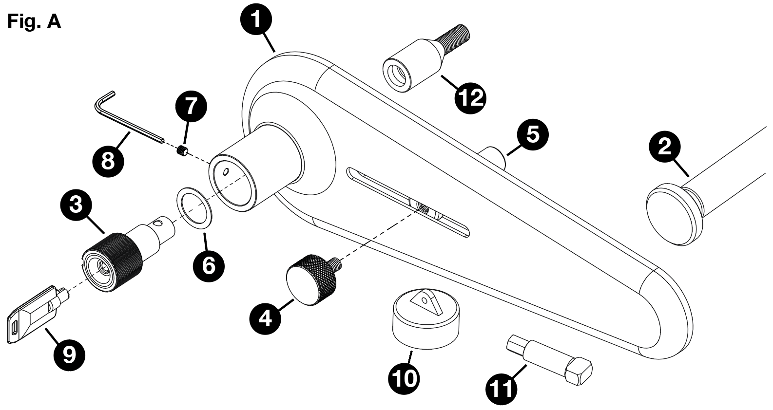
Parts identification & fitting diagram.
Installation
The FullStop® Nemesis Plus Wheel Lock is designed to secure a wheel by locking onto a replacement Wheel bolt, which works alongside an Adjusting Pin and Wheel Bar to then prevent wheel rotation.
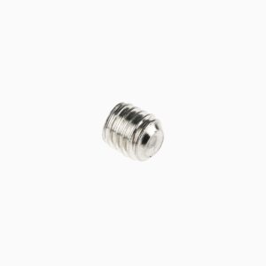
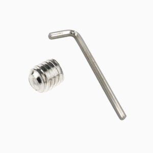
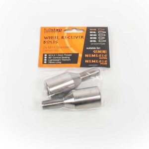
1. Before the product can be used, two of your existing wheel bolts must be removed and replaced with Receiver Wheel Bolts (12). These replacement bolts have been designed to fit the majority of motorhome wheels, however, please check that your existing wheel bolts are of the same specification. The supplied Receiver Bolts (12) have M14 x 1.5mm thread pitch with a 60° conical seating. If in any doubt consult the vehicle manufacturer or wheel supplier BEFORE installation as it is possible to damage the hub of the motorhome if the screw threads do not match. Alternate size wheel bolts are available to purchase, for more information see the ‘Alternative Receiver Wheel Bolts’ section of this manual.
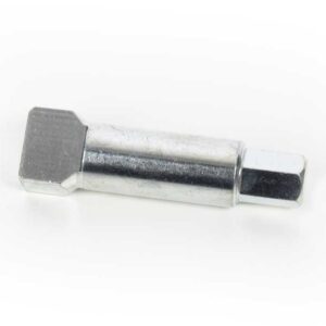
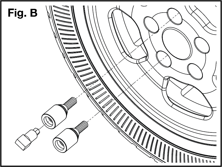
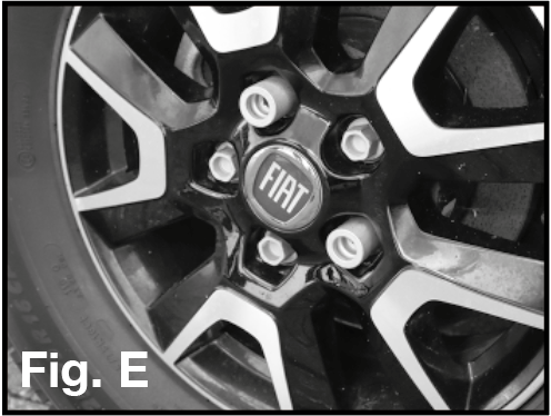
When removing the two required wheel bolts, ensure that the chosen locations are opposite one another (see Fig.B/E), as this will provide two fitting options when installing the Nemesis Plus. Receiver Wheel Bolts (12) can then be fitted using the Wheel Wrench Adapter (11) which enables you to use a standard 19mm wheel wrench (see Fig.B). The Receiver Bolts (12) should be tightened to the correct torque setting for your wheels.
Never install more than the recommended 2 Receiver Bolts per wheel. Do not over-tighten bolts or use an impact wrench.
Only ever install the Nemesis Plus on a non engine driven wheel. On motorhomes this is typically the rear wheels, however if unsure please consult the vehicle manufacturer prior to installation.
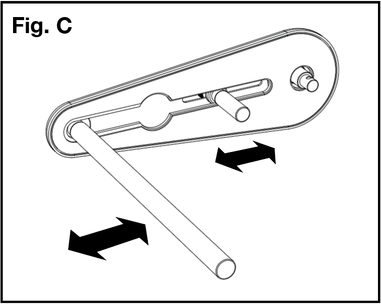
2. To prepare the Nemesis Plus for fitting, the Adjustable Pin (5) and Pin Grip (4) need to be installed into the Shield Plate (1). To do this locate the Adjustable Pin (5) into the wide aperture in the back of the plate and slide it down into position (see Fig.C). Fasten this in place by screwing the Pin Grip (4) into the threaded hole in the top of the Adjustable Pin (5), as shown in Fig. A.
NOTE: When fastening the Pin Grip (4) into the Adjustable Pin (5) be sure not to over tighten. Over tightening may prevent the Pin assembly from sliding correctly along its slot, and could cause damage to the threading on the Adjustable Pin or Pin Grip.
There are many possible configurations for how the Nemesis Plus may fit to a particular wheel. Fig.C shows that the Adjustable Pin (5) and Wheel Bar (2) are designed to slide in or out as necessary, depending on the scale of the wheel and where the Receiver Bolts (12) have been installed in relation to gaps in the wheel’s spokes.
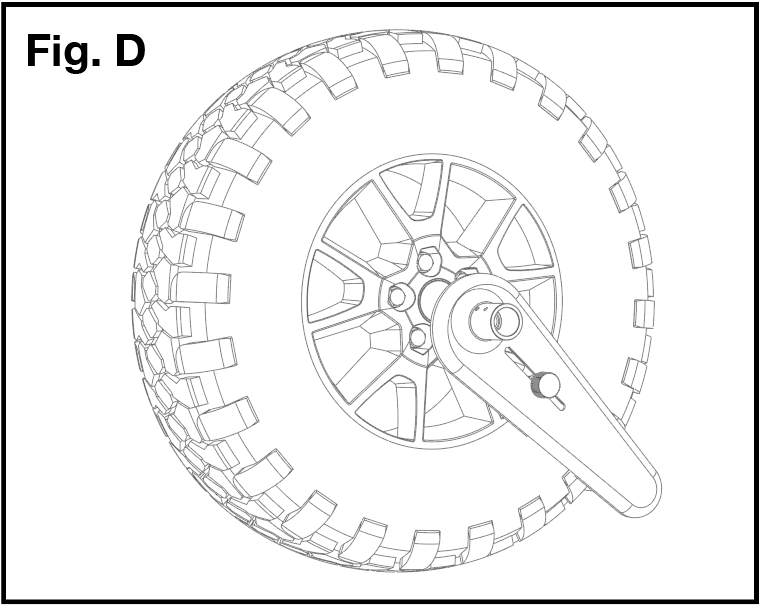
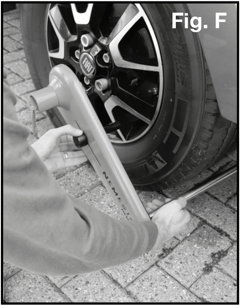
When fitting, the device should be situated on an angle which locates the Adjustable Pin (5) through a gap in the lower part of the wheel, so that the Wheel bar (2) on the outside of the tyre is rested on or close to the ground (see Fig.D/F for guidance). The nature of having two receiver bolts (12) installed will mean that at least one will always be suitably located for the fitting of the lock.
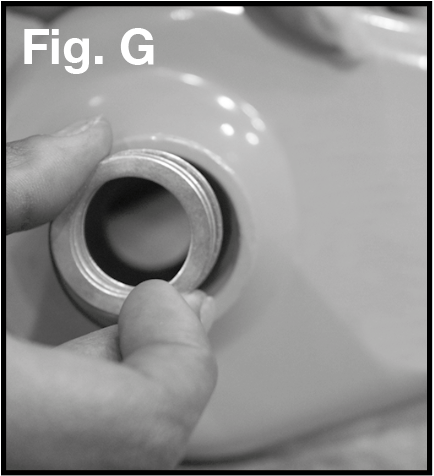
3. Before using the device it may be necessary to add Spacer Rings (6) to ensure that, when fitted, the back face of the Shield Plate (1) is as tight as possible to the face of the wheel when the Locking Portion (3) is locked into a Receiver Bolt (12).
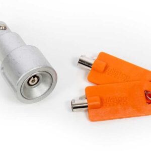
To check this, first fit one of the keys into the Locking Portion (3) and rotate it through 90° clockwise which releases the locking ball bearings. You can now install the Locking Portion (3) through the aperture in the Shield Plate (1) as indicated in Fig. A.
Offer up the assembly to the Receiver Bolt (12) and guide the end of the Locking Portion (3) into a Receiver Bolt (12) as far as it will go. Lock them together by rotating the key anti-clockwise through 90° and remove the key. If the Shield Plate (1) is tight against the face of the wheel then no further adjustment is required. If, however, there is a gap between the back face of the Shield Plate (1) and the face of the wheel, then Spacer Rings (6) must be used. Try to gauge the amount of gap and add the necessary amount of 1mm thickness Spacer Rings (6) between the Shield Plate (1) and the Locking Portion (3) as shown in Fig.A, by inserting into the aperture (Fig.G).
NOTE: If at this stage you find that the Receiver Bolts do not protrude far enough from the wheel to achieve a flush fit of the Nemesis Plus with the tyre, it may be that you require longer Receiver Bolts. See the section ‘Alternative Receiver Wheel Bolts’ for more information.
If you add too many Spacer Rings (6) it will not be possible to fully engage the Locking Portion into the Receiver Bolt and rotate the key to lock it. If this happens, simply remove one Spacer Ring at a time until you achieve a secure fitment.
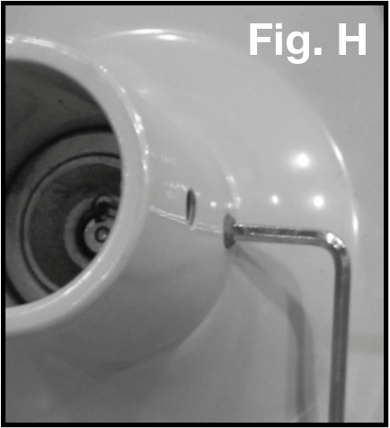
Once satisfied with the fit between the Shield Plate (1) and the face of the wheel, the Spacer Rings (6) can be retained in place by securing the Lock Unit (3) to the Shield Plate (1). Do this by tightening the Locking Portion Hex Screw (7) using the supplied 3mm Hex Key (8) (see Fig.H for guidance).
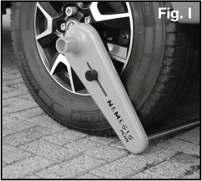
4. The Nemesis Plus is now ready for use (Fig.I). Please check the Receiver Bolt torque setting after the first 100 miles (approx) and at regular intervals thereafter.
MAINTENANCE
Fit protective Lock Cap (10) over the Shield Plate (1) to help prevent ingress of dirt or water.
Grease the lock face and ball bearings before first use, with a light oil such as 3-IN-ONE or equivalent.
Thereafter spray any moving parts of the lock body with a light oil such as 3-IN-ONE or equivalent every eight weeks.
PRODUCT REGISTRATION
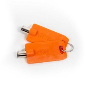
Please store your keys in a safe place and remember to register your product.
Please register within 14 days of purchase. Please retain your original purchase receipt.
ALTERNATIVE RECEIVER WHEEL BOLTS
Various receiver bolt sizes are available for purchase to work in conjunction with the Nemesis Plus Wheel Lock. Please check your motorhome wheel specification or contact your motorhome manufacturer prior to purchasing or attempting to fit any Receiver Bolt. Attempting to fit the incorrect size wheel bolt can cause damage to the wheel hub of the motorhome.
The following receiver wheel bolts are available to purchase:
M14 short wheel bolts
£50.00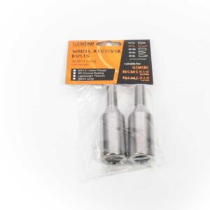
M14 long wheel bolts
£50.00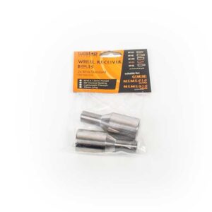
M16 short wheel bolts
£50.00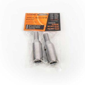
M16 long wheel bolts
£50.00SPARE PARTS
The following spare parts are available to purchase: